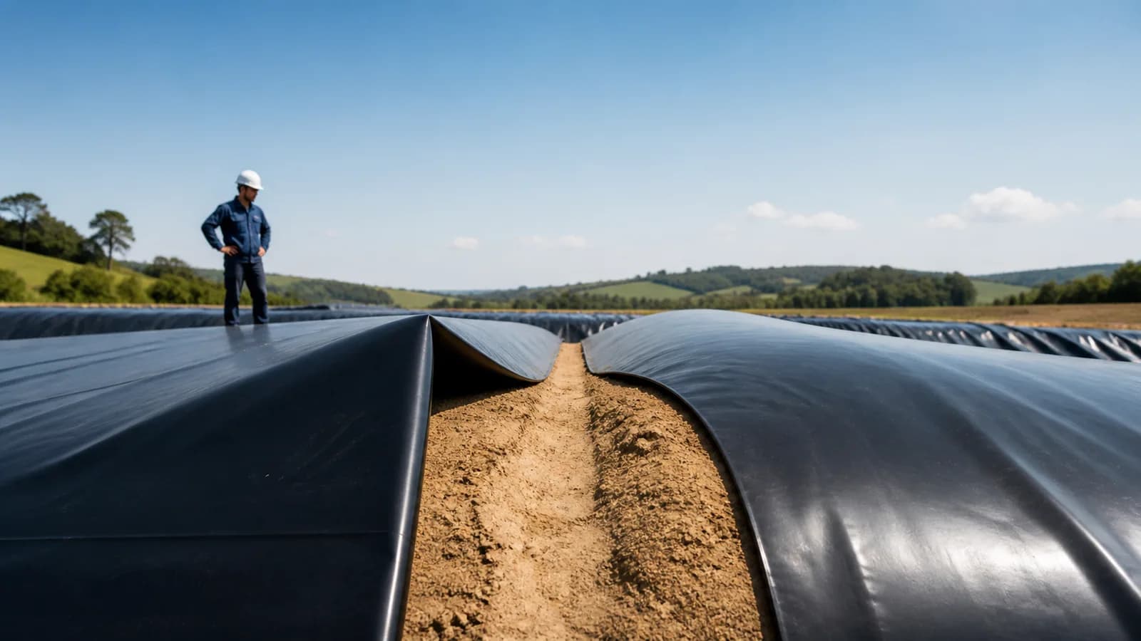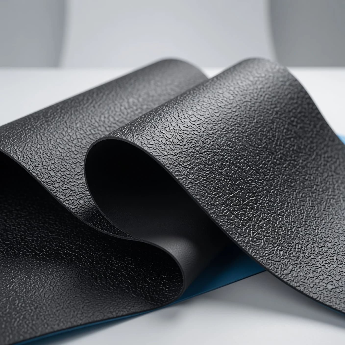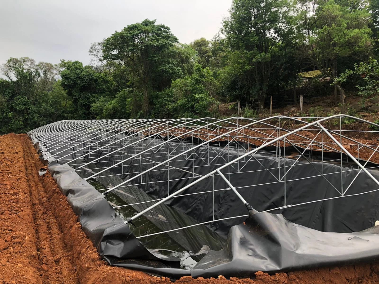
A seam may look uniform while still having low strength or a discontinuity. It may also pass a continuity test without meeting the mechanical criterion defined for the project.
Geomembrane seam control therefore combines checks with different functions. The purpose is not to accumulate tests, but to build traceable evidence that the material, equipment, operator, conditions, and repairs complied with the project plan.
1. Distinguish construction, control, and acceptance
Three responsibilities must be clear in geomembrane contracts:
- Construction Quality Control (CQC): controls performed under the responsibility of the contractor or manufacturer;
- Construction Quality Assurance (CQA): verification that construction complies with design and acceptance criteria;
- designer or responsible professional: defines the system, methods, frequencies, parameters, and treatment of nonconformities.
On smaller projects, one person may perform several activities, but the contract must still state who executes, records, and accepts. Installer experience is essential, but it does not replace documented criteria.
2. Control begins before the first weld
Geomembrane installation must receive enough information to plan panels, seams, details, and test points. Before mobilization, verify:
- specification and version of applicable documents;
- geomembrane type, thickness, finish, and lots;
- drawings of the base, slopes, anchoring, and interfaces;
- permitted welding processes;
- required team qualifications and experience;
- welding equipment and testing instruments;
- instrument calibration and verification;
- recording forms;
- criteria for stopping work due to rain, wind, moisture, or surface conditions;
- test methods, frequencies, and acceptance;
- repair and retesting procedures.
Without this agreement, a field failure becomes a dispute over responsibility instead of a known containment and correction sequence.
3. Release the subgrade and panels before joining
Weld quality does not correct an inadequate base. The subgrade must be firm, even, and free of elements that could puncture or stress the liner. The handoff between civil preparation and installation must be documented.
While unrolling, check:
- lot and roll identification;
- transportation and storage damage;
- position and code of each panel;
- overlap appropriate to the process;
- cleaning and drying of the seam area;
- absence of severe wrinkles or excessive stress;
- weather and material temperature;
- protection against wind and unintended movement.
These records connect received material to its final location and help investigate deviations.
4. Use trial seams to qualify the operating window
Before production, the operator and equipment must demonstrate the ability to form an acceptable seam under current conditions. A trial seam uses the same material and representative parameters and is submitted to the procedure defined in the quality plan.
A new check may be needed after a relevant change in:
- operator;
- equipment or maintenance;
- material lot or type;
- temperature and weather;
- settings, speed, or pressure;
- welding process;
- work resumption after an interruption.
There is no single temperature-and-speed combination valid for an entire project. Adjustment depends on equipment, material, and field conditions.
5. Record the parameters of every seam
The welding log must allow execution to be reconstructed. For each section, record according to the plan:
- seam code and joined panels;
- date and time;
- operator and equipment;
- process used;
- relevant settings;
- ambient and material temperature when required;
- wind, moisture, and surface conditions;
- visual-inspection result;
- associated tests;
- repairs and releases.
A number without a location loses value. Codes must appear on the panel map and as-built record.
6. Understand what visual inspection can show
Visual inspection looks for misalignment, contamination, overheating, wrinkles, channels, apparent discontinuities, irregular extrusion, and incomplete details. It also identifies damage away from seams, such as cuts, punctures, and abrasion.
It is a continuous and necessary stage, but it does not measure strength or find every defect. Approving an installation only “by eye” leaves gaps that other methods were created to cover.
7. Use nondestructive tests to assess continuity
Nondestructive tests follow seams according to their geometry and the specified method.
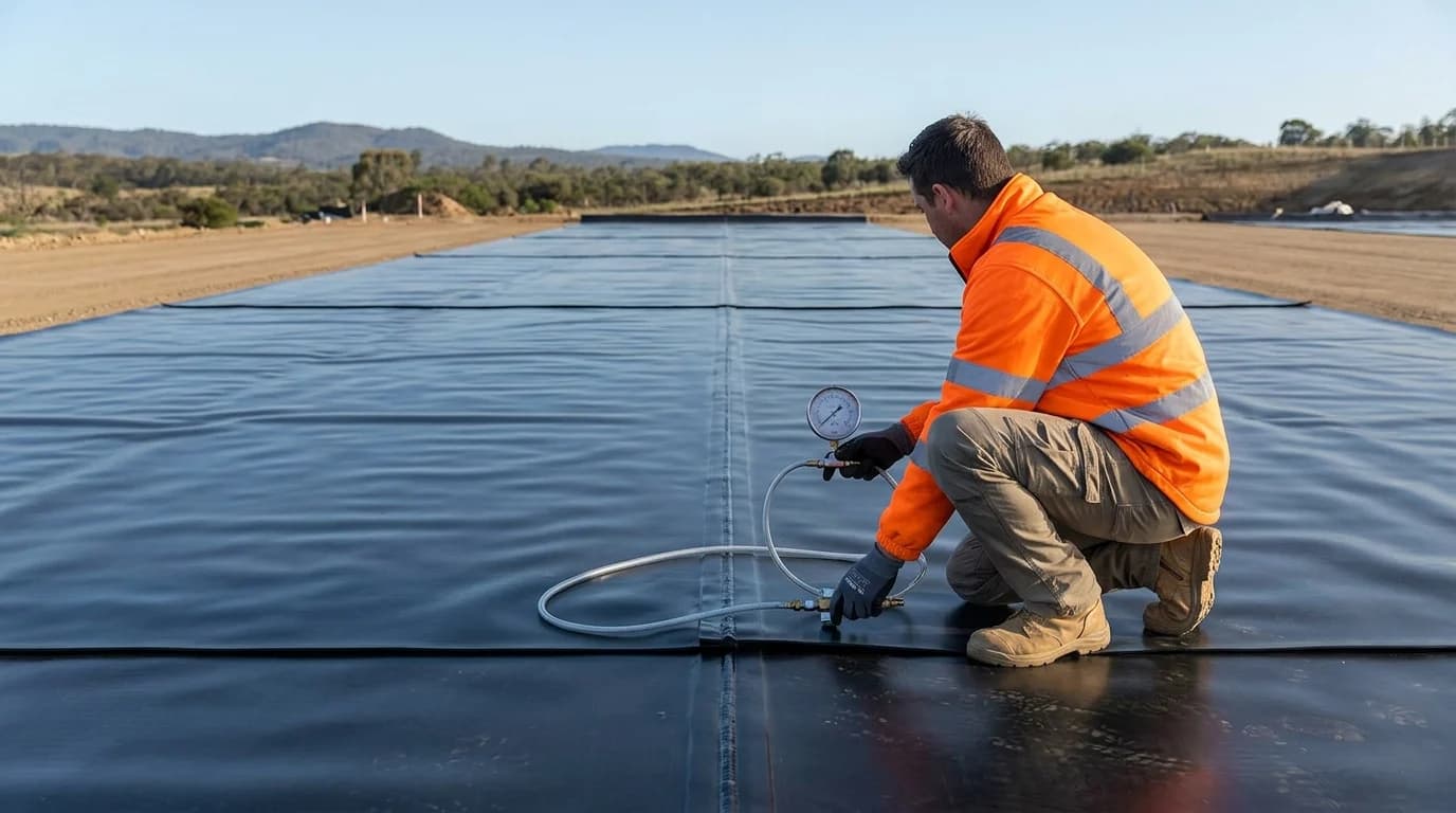
Air channel in a dual-track seam
Dual-track seams form a channel between the joined lines. ASTM D5820 addresses the pressurized-air-channel test. The procedure observes whether the channel maintains the pressure behavior defined in the plan.
This test assesses continuity of the dual seam, but it does not measure shear or peel strength.
Vacuum box
ASTM D5641/D5641M-25 describes vacuum-box evaluation. The technique is useful for seams and repairs whose geometry allows a seal to be formed and leak indications observed.
Corners, irregular surfaces, and details that prevent sealing require another compatible method. An area must not be declared tested when its geometry made the test invalid.
Other methods
Spark testing, air lance, and electrical methods may apply to certain configurations. Selection depends on geomembrane type, support, cover, accessibility, and objective. The method must be planned and performed by a qualified team.
8. Use destructive coupons to assess strength
ASTM D6392-25 describes destructive peel and shear tests for heat-fused seams in nonreinforced geomembranes. Testing produces strength data and separation or deformation behavior that help the quality professional assess the seam.
Sampling is localized. The plan must therefore define:
- frequency and selection of points;
- coupon dimensions and identification;
- field and laboratory specimens;
- conditioning and chain of custody;
- test method and speed;
- criteria for material, thickness, and process;
- treatment of invalid or nonconforming results;
- repair and retest of the sample opening.
GRI-GM13 Rev. 19 incorporated HDPE seam requirements in an appendix and references ASTM D6392. It is unsafe to copy an isolated value without checking edition, thickness, seam type, units, and the complete project criterion.
9. Delimit the extent of a nonconformity
When a coupon fails, the problem does not end at the sample point. The procedure must delimit the potentially affected section, perform further tests according to the plan, and repair or replace the nonconforming area.
A coherent sequence is:
- stop and identify the section;
- preserve operator, equipment, and parameter records;
- locate the limits of nonconformity with additional controls;
- perform the approved repair;
- test the repair with a compatible method;
- update the map and report;
- formally release the area before covering or operation.
Removing the marking after repair destroys traceability. The history must show failure, decision, correction, and acceptance.
10. Look for damage away from seams
Most of a geomembrane surface is not a seam. Punctures may occur during unrolling, ballasting, traffic, pipe assembly, or placement of protective layers.
Electrical Leak Location (ELL) methods are used to locate discontinuities in installed geomembranes under suitable conditions. ASTM D6747 addresses technique selection; ASTM D7002 and ASTM D7007 cover exposed and covered configurations. Applicability depends on preparing the system with an electrical path and compatible conditions.
ELL does not replace seam control and does not automatically work in every structure. It must be anticipated in the design because materials, grounding, metal elements, moisture, and cover affect the method.
11. Protect the accepted area
An accepted seam can still be damaged. After testing:
- restrict traffic and tools on the liner;
- use protection for authorized equipment;
- control temporary ballast;
- plan geotextile or soil placement without dragging materials;
- prevent machine turning and aggregate drops over the liner;
- reinspect areas after work by other teams;
- maintain hold points before covering.
For covered geomembranes, the last opportunity for direct inspection disappears when the next layer advances.
12. Assemble a dossier that supports operation and repair
According to the scope, delivery should include:
- certificates and roll traceability;
- subgrade acceptance;
- panel plan and map;
- trial seams;
- production records;
- nondestructive and destructive results;
- repair map;
- nonconformities and releases;
- calibrations and responsible team;
- as-built record and photographs;
- guidance for inspection, maintenance, and repair.
Documentation is not bureaucracy separate from quality. It is what makes it possible to locate a section, understand construction, and plan a future intervention.
Checklist for contracting and monitoring
Before installation, ask:
- is there a design and CQC/CQA plan;
- who executes and who accepts;
- which processes and equipment will be used;
- how operators will be qualified;
- which conditions suspend welding;
- which tests cover each seam type;
- which frequency and criterion apply;
- how failures will be delimited;
- how repairs will be identified and tested;
- whether the entire surface will be inspected;
- who authorizes covering;
- which documents will be delivered.
Quality is a chain of evidence
A good seam is not defined by appearance, a single test, or team reputation alone. It results from a qualified process, controlled conditions, complementary checks, and traceability through final release.
LJS performs geomembrane installation, including placement, welding, finishing, and field checks according to project scope. Send the design, material, geometry, and quality criteria to align responsibilities before mobilization.
Technical references
- ASTM International — ASTM D6392-25: integrity of heat-fused seams
- ASTM International — ASTM D5641/D5641M-25: vacuum-box evaluation
- ASTM International — ASTM D5820: air-channel test for dual seams
- Geosynthetic Institute — GRI-GM13 Rev. 19
- ASTM International — ASTM D6747-25: selection of electrical leak-location techniques
- USDA NRCS — National Engineering Handbook, Part 645, Subpart J: Geosynthetics
International references support general criteria. The project plan must check applicable Brazilian standards, current editions, contractual specifications, manufacturer recommendations, and local professional responsibility.