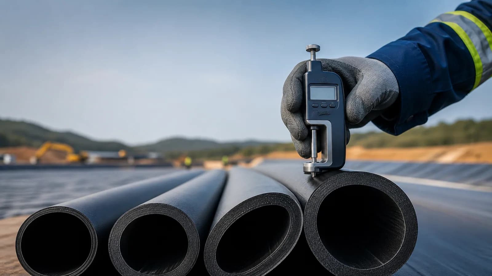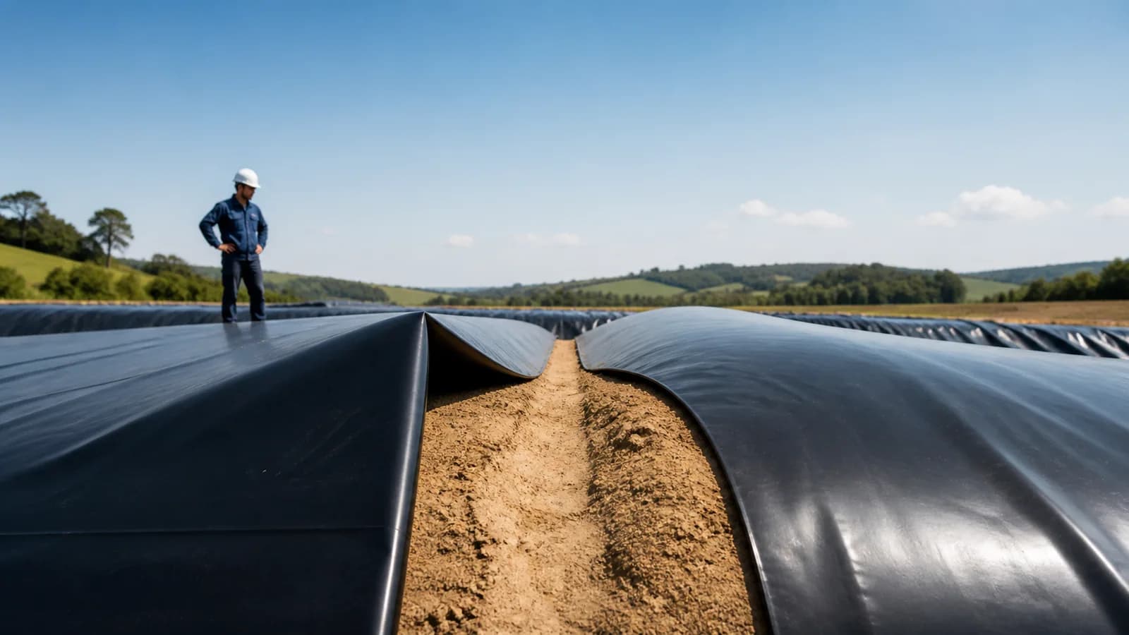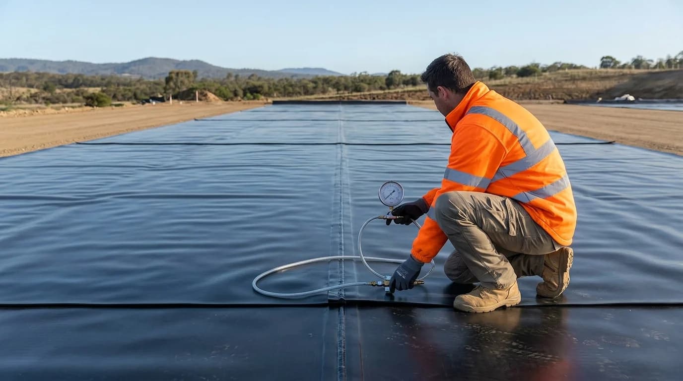
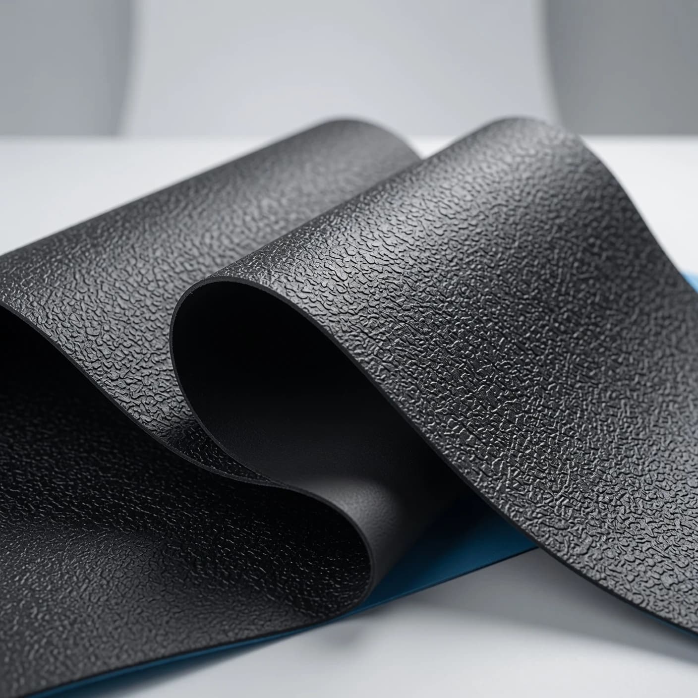
The visual difference between a smooth and a textured HDPE geomembrane is easy to see. The design decision, however, must not be reduced to the idea that “smooth is for flat areas” and “textured is for every slope.”
In systems with soil, geotextile, geocomposite, or another geosynthetic over the geomembrane, each contact forms an interface. Stability depends on how these interfaces behave under the stresses, moisture, and construction conditions of the project.
1. What changes between the two surfaces
A smooth HDPE geomembrane has a relatively uniform surface. It is widely used as a barrier in reservoirs, ponds, channels, landfills, and other structures, according to the system specification.
A textured HDPE geomembrane has roughness produced on one or both sides. This surface may increase sliding resistance for certain combinations of materials and conditions.
The decisive word is “may.” GRI-GM13 Rev. 19, a manufacturing quality-control specification for HDPE geomembranes, warns that asperity height does not represent an expected interface-strength value. Behavior must be assessed for the product and the project materials.
2. Think about interfaces, not the liner alone
Consider a slope with supporting soil, geomembrane, protective geotextile, and a cover layer. There are at least two relevant interfaces:
supporting soil ↔ geomembrane ↔ geotextile ↔ cover
The critical sliding plane may not be where the team expects. A textured geomembrane in contact with a specific geotextile may behave one way, while another geotextile, stress, or moisture condition produces a different result.
The design must map:
- every material in contact;
- the position and inclination of each interface;
- slope length;
- expected normal stresses;
- presence of water, leachate, or another fluid;
- drainage above and below the liner;
- loads during installation, covering, and operation;
- possible deformation and settlement;
- construction sequence.
This approach prevents selecting a surface from a catalog only to discover later that another interface controls stability.
3. When a smooth geomembrane may make sense
A smooth surface may be appropriate when stability analysis, geometry, and system composition demonstrate sufficient performance. Depending on the application, it may also facilitate cleaning, visual inspection, or liquid conveyance.
Its use is common in low-slope areas, but “flat area” does not remove other checks. Hydrostatic pressure, gas uplift, settlement, puncture, wrinkles, traffic, and anchoring remain relevant.
Selection must not be justified only by lower cost or immediate availability. Material, thickness, compatibility, protection, details, and installation control must be confirmed.
4. When texture becomes part of the solution
Texture is mainly considered when interface friction contributes to the stability of slopes or inclined layers. Applications may include landfills, channels, mining, and structures with cover over the liner.
The choice between texture on one or both sides depends on which contacts must be addressed. A textured side facing the wrong direction does not solve the critical interface. Texturing both sides also does not eliminate calculation or testing.
In addition to performance, the design must consider construction. Textured surfaces may affect cleaning, detail welding, inspection, extrusion-material consumption, and panel handling. Main seams and finishes must follow procedures qualified for the product used.
5. Why direct-shear testing is important
ASTM D5321/D5321M addresses direct shear testing of soil–geosynthetic and geosynthetic–geosynthetic interfaces. When a Geosynthetic Clay Liner (GCL) is present, ASTM D6243/D6243M addresses the internal and interface shear strength of GCLs. These tests seek to represent project materials and conditions under defined stresses.
GRI-GM13 states that strength associated with the geomembrane should be determined by product- and material-specific direct shear testing when applicable, or that the waiver should be formalized by the designer with owner agreement before deployment.
For the result to support the decision, the specimen must represent:
- proposed manufacturer and product;
- the smooth or textured side actually used;
- geotextile, geocomposite, or soil in contact;
- relevant moisture condition;
- stresses compatible with the project;
- direction and contact condition;
- interpretation criteria defined by the designer.
A report for another product or a different interface is weak evidence for the current structure.
6. Peak and post-peak do not tell the same story
Geosynthetic interfaces may reach a maximum resistance and then mobilize a lower value after displacement. The designer must decide which parameters represent the analyzed condition, considering allowable deformation, construction process, and consequences of movement.
Using only the largest number in a report, without understanding its origin, may overestimate performance. Interpretation must include the curve, displacement mode, repeatability, specimen preparation, and test conditions.
This article does not replace geotechnical interpretation. Its role is to show why a responsible specification requires more than the words “textured geomembrane.”
7. Water and drainage may change the interface
Water infiltrating between layers may reduce resistance, create pressure, and change the critical plane. In reservoirs and ponds, leakage or groundwater levels may also press against the liner.
The system must assess:
- surface drainage to keep rain away from the slope;
- drainage layer when specified;
- outlets that will not become blocked;
- erosion protection;
- water or gas pressure beneath the geomembrane;
- response during filling and drawdown;
- long-term interface condition.
Texture does not replace drainage. If water has no controlled path, stability may be affected even with a rough surface.
8. Anchoring completes the force path
The force mobilized on the slope must reach a detail capable of resisting it. Trenches, berms, concrete interfaces, terminations, and transitions must be designed and built according to the project.
An anchor trench copied from another project may be insufficient or create stress concentration. The detail depends on geometry, soil, force, filling sequence, and operation.
Traffic, cover placement, or panel tension that introduces unplanned forces must also be avoided before anchoring is complete.
9. Receiving inspection and traceability remain essential
After selection, confirm that the delivered material matches the tested and specified material. Record:
- manufacturer, product, and finish;
- lot and roll numbers;
- nominal thickness;
- textured side or sides;
- manufacturing certificates and results;
- transportation and storage condition;
- planned conformance samples;
- relationship between rolls, panels, and location in the as-built record.
GRI-GM13 is a Manufacturing Quality Control reference. It contains material properties and testing frequencies, but the specification itself explains that it may not be sufficient as a complete document for a specific application. Design, conformance testing, and Construction Quality Assurance remain necessary according to project risk.
10. Avoid five common shortcuts
- “Every slope requires texture.” The surface depends on analysis of the interfaces and the system.
- “Greater roughness always means greater friction.” GM13 rejects this direct equivalence.
- “Texture eliminates anchoring.” Forces still need to be transferred to and resisted by the details.
- “A catalog test applies to every project.” Product, materials, stresses, and moisture must be representative.
- “The geomembrane stabilizes the soil.” Global stability of the structure and slopes is a separate verification.
Surface-specification checklist
Before purchasing, gather:
- plan, sections, and slopes;
- slope height and length;
- materials above and below the geomembrane;
- available geotechnical tests and parameters;
- expected water or leachate at the interfaces;
- construction and operating loads;
- need for cover;
- proposed product and side;
- interface-testing plan;
- anchoring and transition details;
- installation and quality-control plan.
The correct choice is a system decision
Smooth and textured geomembranes are not generic quality levels. They are different surfaces for conditions that must be demonstrated by the design.
LJS can support material supply and geomembrane installation according to the design report, tests, and site conditions. Send sections, contact materials, and the specification to organize an initial assessment.
Technical references
- Geosynthetic Institute — GRI-GM13 Rev. 19: smooth and textured HDPE geomembranes
- Geosynthetic Institute — official GRI specification index
- ASTM International — ASTM D5321/D5321M-26: direct shear of geosynthetic interfaces
- ASTM International — ASTM D6243/D6243M-26: internal and interface shear strength of GCLs
- ASTM International — ASTM D7702/D7702M: evaluation of direct shear results
- USDA NRCS — Pond Sealing or Lining, Code 521
GRI, ASTM, and NRCS references guide technical criteria but do not replace Brazilian standards, geotechnical design, permitting, and project-specific specifications.