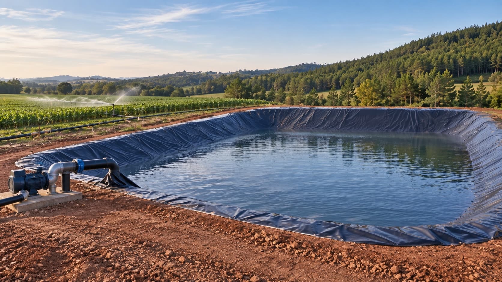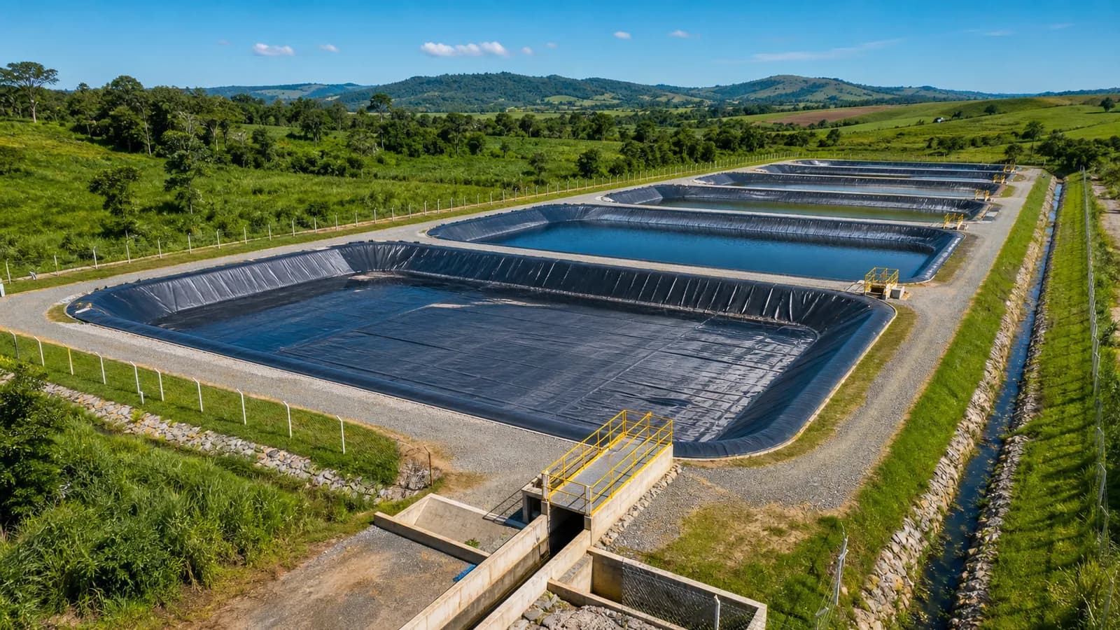

Reliable lining does not begin when the sheet is unrolled. It begins when the team understands what will be stored, how the structure will operate, and which ground conditions may place pressure on the system over time.
In ponds, cisterns, and reservoirs, the geomembrane is part of an assembly. The base, slopes, drainage, anchoring, piping, welds, protection, and inspection routine must work together. When one of these decisions is left for the field, the likelihood of rework, improvised details, and vulnerable points increases.
This guide organizes the decisions that deserve attention before, during, and after installing a smooth HDPE geomembrane.
1. Begin with the purpose of the reservoir
Before defining material or thickness, describe the actual operation of the structure:
- which fluid will be contained;
- normal volume and maximum operating level;
- filling and drawdown frequency;
- whether the geomembrane will remain exposed or receive cover;
- location of the inlet, outlet, overflow, and inspection points;
- which machines, animals, or teams will circulate nearby;
- whether gas or water may accumulate beneath the liner.
A clean-water reservoir, manure-storage basin, and effluent pond may have similar geometry but different operating requirements. The specification must reflect the use, fluid composition, and consequences of a shutdown.
2. Treat ground and geometry as part of the system
The geomembrane follows the surface on which it is installed. Site investigation, geometry, and stability are therefore not separate from lining design.
It is important to assess:
- base regularity and bearing capacity;
- stones, roots, sharp materials, or organic soil;
- slope stability;
- possibility of differential settlement;
- groundwater level and need for drainage;
- access for equipment, roll deployment, and team movement;
- space for anchoring and edge finishes.
Technical references such as the U.S. Bureau of Reclamation chapter on geomembranes reinforce that design, construction, and monitoring must be treated as an integrated process. The practical rule is simple: a liner does not correct an unstable base or eliminate unanticipated pressure.
3. Prepare the base so defects are not transferred to the liner
At the start of installation, the subgrade must provide a firm, even surface without elements capable of puncturing the sheet or concentrating stress. Angular stones, clods, roots, debris, and standing water must be addressed before the work area is released.
Depending on site conditions, the system may require grading, compaction, a selected soil layer, or geotextile protection. The decision must consider base type, expected loads, and potential damage during installation and operation.
Formal base inspection creates a clear hold point: geomembrane placement begins only when the surface is ready to receive it.
4. Specify performance, not merely “a liner”
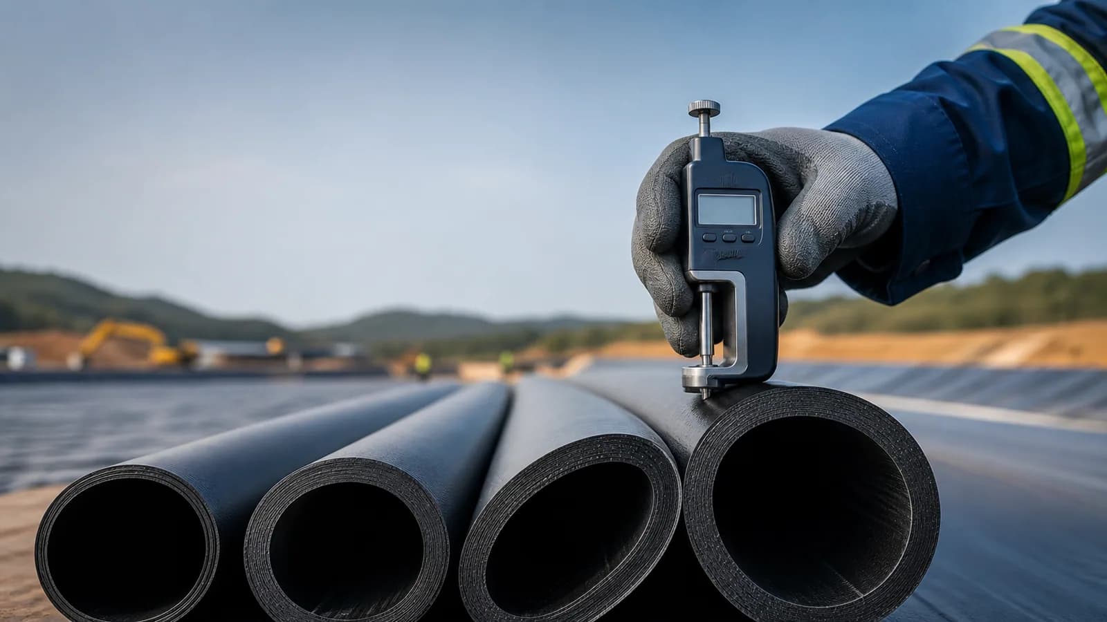
HDPE geomembrane is an engineered material. The specification must identify properties and conformance criteria compatible with the design and define how receiving, storage, and traceability will be controlled.
GRI-GM13, published by the Geosynthetic Institute, compiles test methods, properties, and testing frequencies for smooth and textured HDPE geomembranes. Revision 19 also incorporated in an appendix the HDPE seam requirements previously associated with GRI-GM19. Its general manufacturing requirements may not be sufficient for every specific situation. In other words, compliance with a product reference does not replace system design.
The choice between a smooth and textured surface, for example, depends on interaction with slopes, soils, geotextiles, and protective layers. Thickness also must not be selected in isolation; it must respond to expected installation, exposure, deformation, and use conditions.
5. Resolve anchoring and interfaces before welding
Many critical points occur where the geomembrane meets another project element. Hydraulic inlets and outlets, pipes, boxes, concrete structures, changes of plane, and anchor trenches require defined details before construction.
Panel planning should also seek to:
- reduce unnecessary cuts;
- avoid complex intersections of multiple seams;
- position seams consistently with geometry;
- allow thermal movement without creating severe folds;
- maintain safe routes for the team and equipment.
Resolving these interfaces during design reduces improvised decisions and facilitates inspection of finishes.
6. Control installation conditions
The performance of geomembrane installation depends on a controlled sequence: receiving, roll deployment, positioning, cleaning joining areas, equipment adjustment, welding, testing, and repairs.
Temperature, wind, moisture, dust, and surface condition affect construction. The team must therefore record work-area conditions and adjust the process according to the material, equipment, and approved procedure.
HDPE also responds to temperature changes. Planning must consider expansion, contraction, and wrinkles, especially under direct sunlight or before later placement of cover layers.
7. Inspect seam continuity and strength
Looking at a seam is not enough to declare compliance. A control plan must combine visual inspection, nondestructive continuity tests, and destructive strength samples according to the design and applicable procedure. Continuity tests evaluate the joined path; coupon tests evaluate strength and failure mode. One control layer does not replace another.
ASTM D6392 describes destructive peel and shear tests for assessing the integrity of heat-fused seams in nonreinforced geomembranes. For new specifications, the current GM13 edition must be checked alongside this method and the project quality plan.
In practice, the quality record must answer:
- who performed each section;
- which equipment and settings were used;
- when and under which conditions the seam was made;
- which tests were performed and what results were obtained;
- where repairs occurred and how they were verified.
This history makes delivery traceable and supports future inspections or interventions.
8. Protect the geomembrane after installation
An accepted liner can still be damaged by improper traffic, tools, materials dropped onto the surface, or later project stages. The protection plan must remain active until the work area is complete.
Where geotextile or soil cover is used, placement must avoid displacement, folds, and impact. For exposed structures, operation must control access, vegetation, floating objects, and work near the edges.
Filling and startup must also follow the design sequence. A coordinated transition from installation to use reduces the risk of placing a structure into service with hidden outstanding issues.
9. Plan inspection, maintenance, and repairs
The system must remain observable after handover. The routine may include inspection of edges, anchoring, hydraulic points, exposed areas, and locations subject to movement or wear.
When damage is identified, first record its location, extent, and surrounding conditions. A qualified professional must define the repair method, and the section must be verified again before returning to operation.
After-sales service, maintenance, and repairs are not only a response to failures: they are part of the strategy for preserving performance and documenting the service life of the structure.
Checklist for speaking with the technical team
Before requesting a proposal, gather as much as possible of the following information:
- structure purpose and stored fluid;
- desired volume or approximate dimensions;
- site location and access;
- photographs of the area, base, and slopes;
- current ground condition;
- planned inlet, outlet, and overflow points;
- need for cover or additional protection;
- expected schedule and operating constraints;
- existing design, if available.
With this set, the initial assessment becomes more objective and helps separate material supply, civil preparation, installation, hydraulic components, and quality control.
The most important decision is to think about the whole system
Geomembrane, welding, and finishes are visible parts of lining, but the outcome begins with earlier decisions. Purpose, base, geometry, drainage, interfaces, protection, and inspection determine whether the system can be built and operated with control.
If your project involves a pond, cistern, manure-storage basin, or reservoir, LJS can assess the scenario and organize the scope of lining ponds, manure-storage basins, and reservoirs, from diagnosis to field execution.
Technical references
- Geosynthetic Institute — GRI-GM13: specification for HDPE geomembranes
- Geosynthetic Institute — GRI specifications for geomembranes and seams
- ASTM International — ASTM D6392: integrity of heat-fused seams
- U.S. Bureau of Reclamation — Design Standards No. 13, Chapter 20: Geomembranes
- USDA NRCS — Pond Sealing or Lining, Code 521
These references support general technical criteria. They do not replace project-specific design, permitting, applicable Brazilian standards, manufacturer guidance, or assessment of actual site conditions.