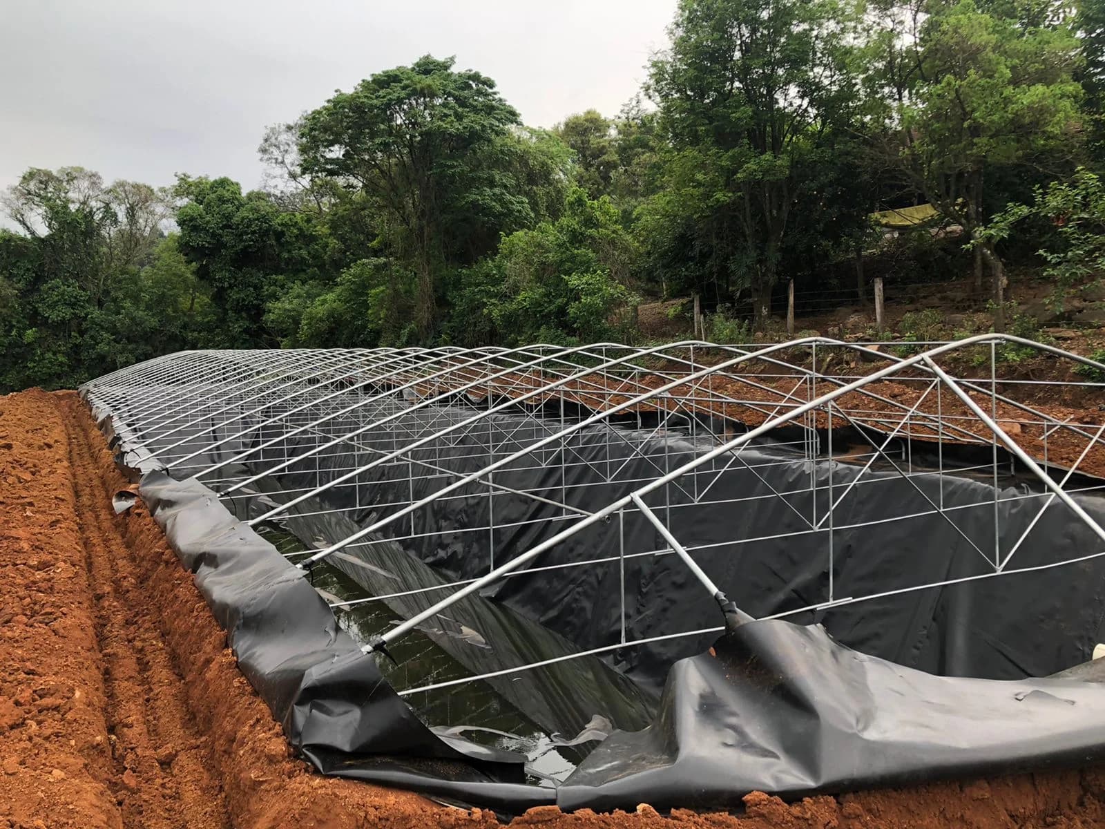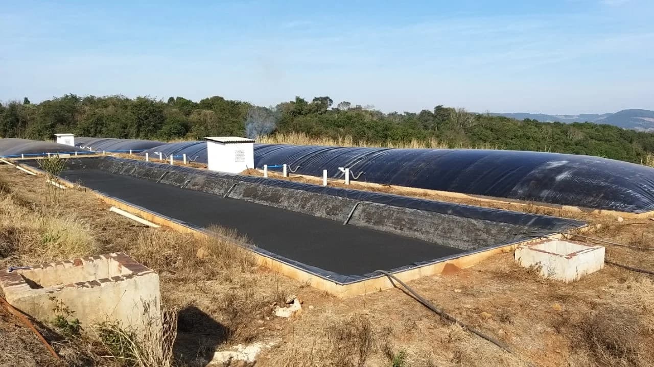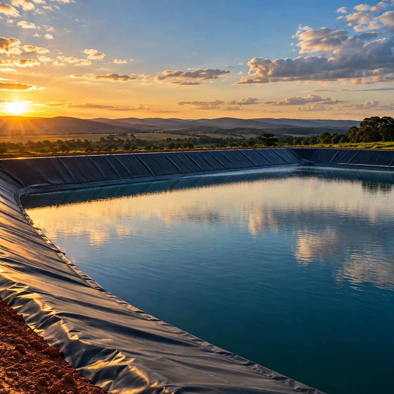

No layer in a landfill works alone. The base barrier must connect to leachate drainage, gas collection, stormwater management, cell operation, and environmental monitoring.
Reducing this system to the purchase of a geomembrane hides the highest-risk points: the ground interface, puncture protection, hydraulic details, seam construction, advancement of the drainage layer, and traffic during operation.
1. Begin with design and permitting
The Brazilian National Solid Waste Policy distinguishes rejects, waste, and environmentally appropriate destinations. Landfill configuration depends on the received waste, size, site, technology, design, and conditions established by permitting.
The Funasa Technical Guidance Manual for Solid Waste Program Proposals lists among the design components unit lining, stormwater drainage, leachate drainage and treatment, gas drainage and treatment, monitoring, operating control, maintenance, and closure.
Before specifying materials, gather:
- permit and conditions;
- design report and construction drawings;
- waste classification and characterization;
- geotechnical and hydrogeological investigation;
- service life and cell phasing;
- water balance and leachate estimate;
- stability criteria;
- Construction Quality Assurance (CQA) plan;
- planned operation, monitoring, and closure.
Landfill construction and lining must respond to these documents, not replace them.
2. Prepare a stable, drained foundation
The subgrade supports the barrier system and loads that will accumulate. Earthworks, grading, and compaction must produce geometry, slopes, and bearing capacity compatible with the design.
Release must verify:
- elevations and slopes;
- surface stability and uniformity;
- absence of stones, roots, and puncturing objects;
- moisture and compaction control according to the specification;
- treatment of unsuitable soil, settlement, or seepage;
- groundwater drainage when specified;
- connection to sumps, trenches, and details;
- condition after rain and before unrolling.
If the base deforms, erodes, or concentrates stress, the liner follows the problem. The hold point between earthworks and geosynthetics must be formal.
3. Understand the barrier system
A barrier may combine low-permeability compacted soil, a Geosynthetic Clay Liner (GCL), geomembrane, and other components. The sequence and criteria depend on the design and permit.
The geomembrane acts as a low-permeability barrier. Compacted soil or GCL may provide a complementary function, including limiting flow if a discontinuity occurs. This combination is called a composite barrier when elements are designed to work in contact.
Performance depends on:
- layer continuity;
- quality of contact between components;
- chemical compatibility with leachate;
- expected deformation and settlement;
- puncture resistance;
- interface stability;
- details at drains, sumps, pipes, and structures;
- construction and quality control.
No geomembrane thickness alone guarantees the behavior of an entire landfill.
4. Select the geomembrane for system conditions
HDPE geomembranes are used in landfill barriers because of their engineering properties and field-welding capability. GRI-GM13 is a manufacturing quality-control reference for smooth and textured HDPE geomembranes.
The specification must assess:
- compatibility with leachate and temperature;
- thickness and mechanical properties;
- resistance to stress cracking, puncture, and expected exposure;
- smooth or textured surface;
- interface stability on the base and slopes;
- certificates, lots, and conformance testing;
- field welding and testing;
- protection during construction and operation.
On slopes, texture may contribute to sliding control, but asperity height does not automatically equal strength. Direct shear tests must represent the project product, geotextile, soil, stresses, and moisture.
5. Give geotextile a clear function
Geotextile is not a generic layer “for reinforcement.” Depending on position and specification, it may provide protection, filtration, or separation.
Over the geomembrane, a nonwoven geotextile may help reduce puncture risk from aggregate and loads. Sizing must consider particle size, angularity, drainage-layer thickness, contact pressure, deformation, and installation sequence.
Around pipes or aggregate, a filtration geotextile must allow liquid to pass while retaining particles according to design criteria. An unsuitable material may clog or allow fines to migrate.
Mass per unit area alone does not describe all these functions. Relevant properties and tests must appear in the design report.
6. Collect leachate without overloading the barrier
Leachate results from water passing through waste and liquids released by the waste mass. Drainage over the barrier seeks to collect it and convey it to storage and treatment while limiting hydraulic head.
The system may include:
- mineral drainage layer or geocomposite;
- perforated drainage pipes;
- branches and collectors;
- sumps or pumping wells;
- inspection and cleaning structures;
- storage and treatment;
- flow and quality measurement.
Pipe diameter, spacing, slope, and strength depend on flow, drainage material, loads, and maintenance access. The pipe must withstand construction and operation without unacceptable loss of section or blockage.
Leachate treatment and destination must comply with the permit and discharge or transfer conditions. Brazilian CONAMA Resolution 430 establishes conditions and standards for effluent discharge, but application depends on classification, receiving water body, water-use authorization, and permitting.
7. Keep clean water away from the waste mass
Every rainfall event entering an active cell may increase leachate generation. Stormwater drainage, operational cover, and phasing help separate clean water from water that contacted waste.
Planning must address:
- perimeter channels and downchutes;
- platform grades;
- erosion protection;
- daily, intermediate, and final cover;
- size of the operating face;
- preparation for intense events;
- inspection and cleaning of devices;
- prevention of mixing between stormwater and leachate drainage.
This control reduces pressure on collection, pumping, and treatment. It also protects slopes and exposed layers during construction.
8. Integrate gas collection
Waste decomposition produces gas that requires a controlled route. Vertical and horizontal drains, wellheads, piping, and flaring or recovery systems must be coordinated with cell advancement and the barrier.
Penetrations and interfaces cannot be improvised over the geomembrane. Besides sealing, the design must consider waste settlement, relative displacement, condensate, access, and maintenance.
Gas beneath a cover layer may also create pressure. Drainage, venting, and final-cover anchoring must be analyzed together.
9. Control interfaces during construction
Much damage occurs after the geomembrane has been welded. Aggregate dropped from excessive height, machine turning, dragged geotextile, or unprotected pipe support may puncture or displace the system.
The construction plan must establish:
- authorized equipment and routes;
- minimum protective thickness before traffic according to design;
- placement and spreading method;
- aggregate drop-height limit;
- sequence for geotextile, drainage, and pipes;
- hold points and inspections;
- response to rain and surface contamination;
- treatment of wrinkles and displacement;
- prohibition on covering unreleased areas.
These values must not be published as generic numbers. They depend on material, equipment, loads, and system testing.
10. Verify seams, surface, and repairs
Geomembrane control combines:
- visual inspection;
- trial seams;
- operator, equipment, and parameter records;
- nondestructive continuity tests;
- destructive strength samples;
- repair location and testing;
- inspection of the entire surface;
- electrical leak-location methods when specified.
The guide on geomembrane weld quality control details each layer. At landfills, documentation must also coordinate drainage-layer advancement so no area is covered without acceptance.
11. Monitor from the beginning of operation
The landfill must remain observable. Depending on the permit and design, the monitoring plan may include:
- leachate flow and characteristics;
- sump levels;
- treatment performance;
- groundwater and surface water;
- gas;
- settlement and stability;
- stormwater drainage and erosion;
- cover integrity;
- events, nonconformities, and maintenance.
Operating data help identify changes in behavior before they become major failures. They also inform new-cell and closure planning.
12. Prepare for closure while the landfill operates
Final cover must reduce infiltration, control gas, accommodate settlement, resist erosion, and allow maintenance. It may include a barrier, drainage, protective soil, and vegetation according to design.
Connections between final cover, slopes, channels, and existing structures must be detailed. Closure does not eliminate collection, treatment, and monitoring; these activities continue for the period defined in the permit and plan.
Scope-review checklist
Before pricing geosynthetics or installation, confirm:
- current construction design and permit;
- waste classification;
- geotechnical and hydrogeological investigation;
- barrier composition and sequence;
- materials and interface testing;
- leachate system and maintenance access;
- stormwater drainage and phasing;
- gas collection;
- penetration, sump, and anchoring details;
- CQA plan and acceptance criteria;
- geomembrane protection during construction;
- as-built record, operation, monitoring, and closure.
Performance lies in the connections
Geomembrane, geotextile, and drainage pipe perform specific functions, but the result depends on their interfaces and on how the landfill is constructed and operated.
LJS supplies and installs geosynthetic systems defined by the landfill construction and lining design. For an initial assessment, send the design report, sections, quantities, permit, and quality criteria.
Technical references
- Brazil — Law 12,305/2010, National Solid Waste Policy
- CONAMA — Resolution 404/2008 for small sanitary landfills
- Funasa — Technical Guidance Manual for solid-waste proposals
- CONAMA — Resolution 430/2011 on effluent-discharge conditions and standards
- IEMA — technical instructions for sanitary landfills
- Geosynthetic Institute — GRI-GM13 Rev. 19
- U.S. EPA — Quality Assurance and Quality Control for Waste Containment Facilities
Brazilian sources support general design and environmental-control components. The international reference supports CQA practices without replacing legislation, standards, and permitting applicable in Brazil.