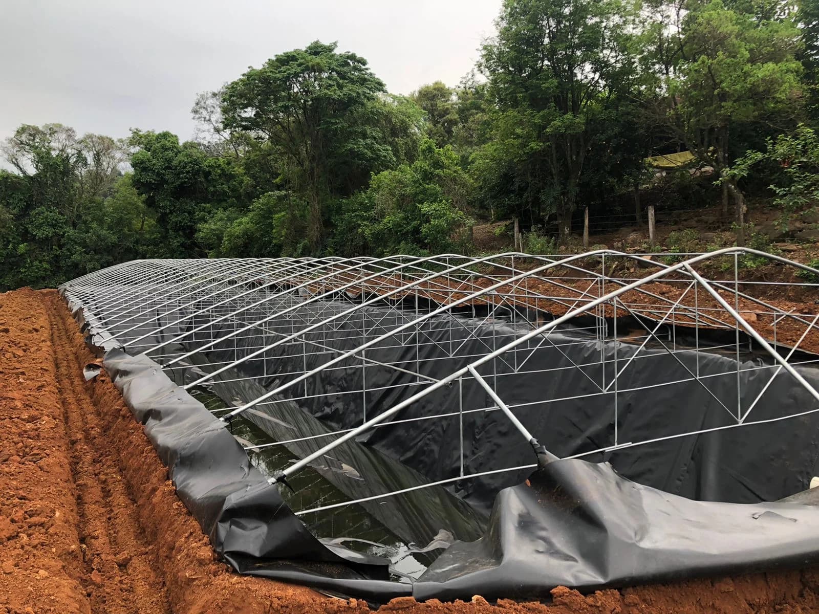
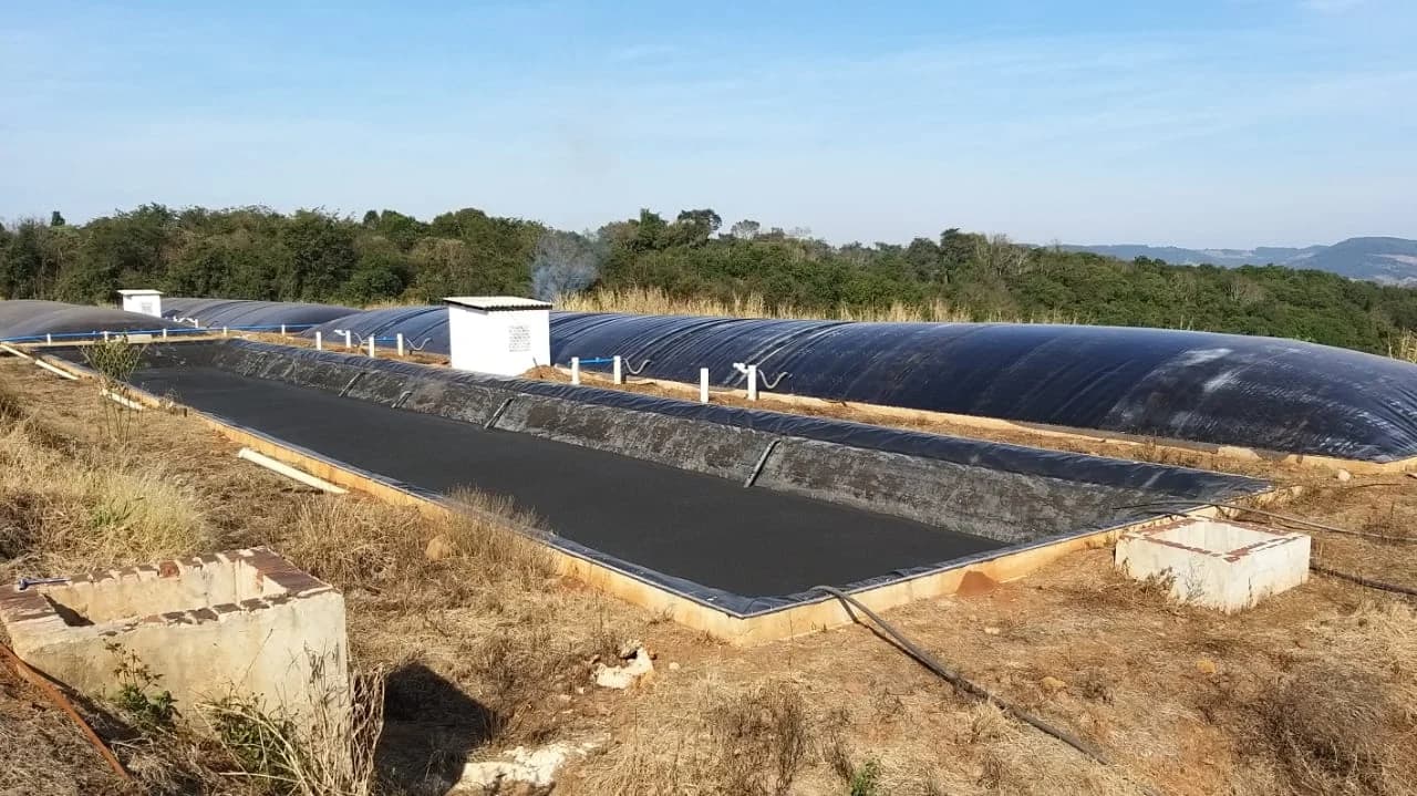
The installation of geomembranes in geotechnical and hydraulic structures—such as reservoirs, wastewater treatment ponds, landfills, and containment basins—is frequently treated merely as a rapid assembly task for plastic sheets. However, the polyethylene liner is only one element of a continuous containment barrier. Its mechanical behavior and long-term durability depend directly on the support provided by the subgrade, thermal conditions during deployment, and the rigor of field inspection routines.
Premature failures in lining systems rarely stem from intrinsic defects in virgin polyethylene resin; the majority of issues arise from mechanical punctures caused by unremoved stones in the base, excessive thermal stress, entrapped wrinkles, or seams executed outside the proper operational window. Coordinating installation requires a systematic method that combines civil works inspection, safe panel handling, and end-to-end traceability.
Formal subgrade acceptance: the indispensable foundation of the barrier
Whether composed of high-density polyethylene (HDPE) or linear low-density polyethylene (LLDPE), geomembranes adapt to hydrostatic stresses by conforming to the supporting ground. If the base features localized irregularities, fluid pressure creates flexural stress and concentrated puncture points that reduce the material's long-term design life.
Before authorizing the delivery and unrolling of coils inside the basin, the inspection and installation teams must formalize subgrade acceptance. This process of how to prepare the ground for geomembrane installation includes verifying:
- Surface uniformity: elimination of roots, stumps, angular gravel, vegetation residue, and sharp debris.
- Compaction degree: the foundation must be firm enough to support construction equipment traffic and liquid head without undergoing excessive differential settlement.
- Absence of standing water and unstable moisture: saturated soils can cause deformation under liner dead weight or trap moisture that generates vapor uplift beneath the lining once sealed.
- Cushioning layer requirements: in stony soils or wherever fine grading cannot fully mitigate puncture risks, installing a nonwoven geotextile underneath the liner serves as a vital mechanical protection layer.
Deployment logistics and thermal accommodation
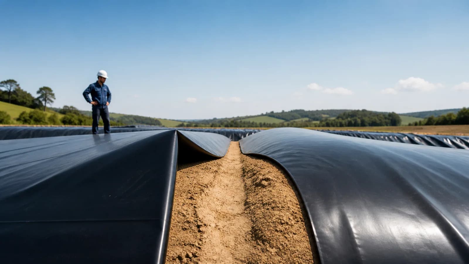
Polyethylene exhibits a high coefficient of linear thermal expansion. During midday hours under direct sunlight, a black liner can reach high surface temperatures and expand, generating pronounced wrinkles and waves. At night and during the early morning hours, cooling causes the material to contract with substantial tensile force.
If installation is executed by pulling panels taut during hot periods, subsequent nighttime contraction places seams and anchor trenches under severe continuous tension, inducing critical stress concentrations along interfaces. Conversely, if excess slack is left that turns into trapped folds under liquid head, preferential stress pathways and high susceptibility to environmental stress cracking (stress cracking) are introduced.
To balance thermal effects during field deployment:
- Panel orientation: on slopes, panels should always be deployed parallel to the line of maximum slope whenever possible, avoiding horizontal cross-seams across the lower third of the incline.
- Immediate temporary ballasting: each unrolled panel must be secured immediately with clean, soft sandbags devoid of sharp edges to prevent wind uplift.
- Controlled slack: incorporate calculated slack (slack) that accounts for the anticipated temperature swing between seaming conditions and the submerged operating temperature of the facility.
Perimeter fixation: sizing and backfilling the anchor trench
The upper perimeter of the geomembrane must be anchored to support both the dead weight of the sheet along the slope and transient loads from wind, thermal fluctuations, and soil cover layers.
The standard configuration is an anchor trench excavated along the slope crest. The trench geometry—depth, width, and setback distance from the crest edge—must be detailed in the geotechnical and engineering design. During construction, three detailing factors are decisive:
- Safe crest setback: the trench must never be excavated right at the edge of the slope, as tensile pullout forces can trigger shear failure and slumping of the soil wedge.
- Rounding edges: the trench leading edge must be chamfered or manually rounded to remove sharp corners that could shear the sheet under tension.
- Backfill compaction: soil returned to the trench over the liner must be free of sharp stones and compacted in shallow lifts to ensure adequate pullout friction through soil interlock.
On vertical rigid structures, such as concrete sumps, monitoring vaults, and perimeter headwalls, mechanical anchoring requires batten strips (stainless steel or aluminum), closed-cell elastomeric gaskets, and mechanical or chemical anchors torqued to specified limits.
Seaming techniques and operational windows
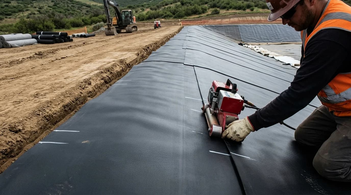
Joining geomembrane sheets must reconstitute the physical and chemical continuity of the barrier. In the field, two thermal fusion methods are utilized by certified crews:
Hot-wedge welding
Used for long longitudinal seams between adjacent panels. Automated self-propelled equipment pulls overlapping edges, heats both contact surfaces simultaneously by direct conduction with a heated wedge, and fuses them under continuous pressure rollers. Modern hot-wedge welders produce a dual-track seam with an enclosed central air channel, allowing for non-destructive pneumatic pressure testing.
Extrusion welding
Used primarily for detail work: corners, pipe penetrations, T-joints, and patches over punctures or wrinkles. A handheld extruder preheats the panel surfaces with hot air and applies a molten bead of compatible virgin resin under the pressure of a profiled Teflon shoe. Prior to extruding, the liner surface must be mechanically abraded with a grinder to remove surface oxidation and wax without excessively gouging the sheet thickness.
Adverse weather demands immediate suspension of seaming. Rain, heavy fog, excessive wind-blown dust, or ambient temperatures outside manufacturer-certified limits impair thermal control, leading to cold welds, lack of fusion, or thermal degradation of the polymer matrix.
Construction Quality Control (CQC) and testing protocols
No phase of geomembrane installation should be signed off without comprehensive, auditable field quality control documentation. Protocol extends far beyond simple visual inspection, pairing daily operational qualification with standardized mechanical and integrity tests:
- Trial seams (startup test strips): prior to beginning work each morning and following lunch breaks, each operator and welding unit must produce trial welds under current environmental conditions. These strips are immediately cut and tested in a field tensiometer for shear and peel resistance. Production welding proceeds only if failure occurs in the parent sheet outside the seam zone (Film Tear Bond — FTB mode).
- Pneumatic air pressure testing (dual seam): both ends of the central air channel created by the hot-wedge welder are sealed using a test needle and pressure gauge. The channel is pressurized with compressed air. An unacceptable pressure drop after the specified dwell time indicates a leak along the seam run, requiring pinpointing and remediation.
- Spark testing or vacuum box testing: on extrusion welds and structural penetrations where a dual channel does not exist, seam continuity is verified using a vacuum box with an applied surfactant solution or a calibrated high-voltage spark tester.
- Laboratory destructive testing: periodic field seam samples are taken at linear intervals specified by the design engineer for quantitative laboratory testing; the resulting sampling holes are sealed with an extrusion-welded patch and re-inspected.
To examine testing tolerances, acceptance thresholds, and mechanical strength requirements for each weld classification, refer to our detailed guide on geomembrane weld quality control.
Interface with adjacent layers and embedded structures
In landfills and large-scale containment facilities, geomembranes do not function in isolation. They interact with foundation soils, aggregate drainage layers, and fluid or biogas recovery systems. The selection between smooth or textured HDPE geomembrane is governed by interface friction requirements along slope profiles: steep embankments demand textured surfaces to mitigate sliding risks for overlying mineral or geosynthetic strata.
Furthermore, connections to concrete discharge structures or HDPE penetration pipes statistically represent the most common points of non-compliance. These details require prefabricated boots made of identical sheet resin, secured with vulcanized mastic tape, stainless steel clamp bands, and extrusion fillet welds to ensure structural movements do not tear the primary liner.
A durable geomembrane installation relies on rigorous alignment between an engineered subgrade, careful panel deployment, strict adherence to thermal windows, and traceable verification for every linear meter of seam.