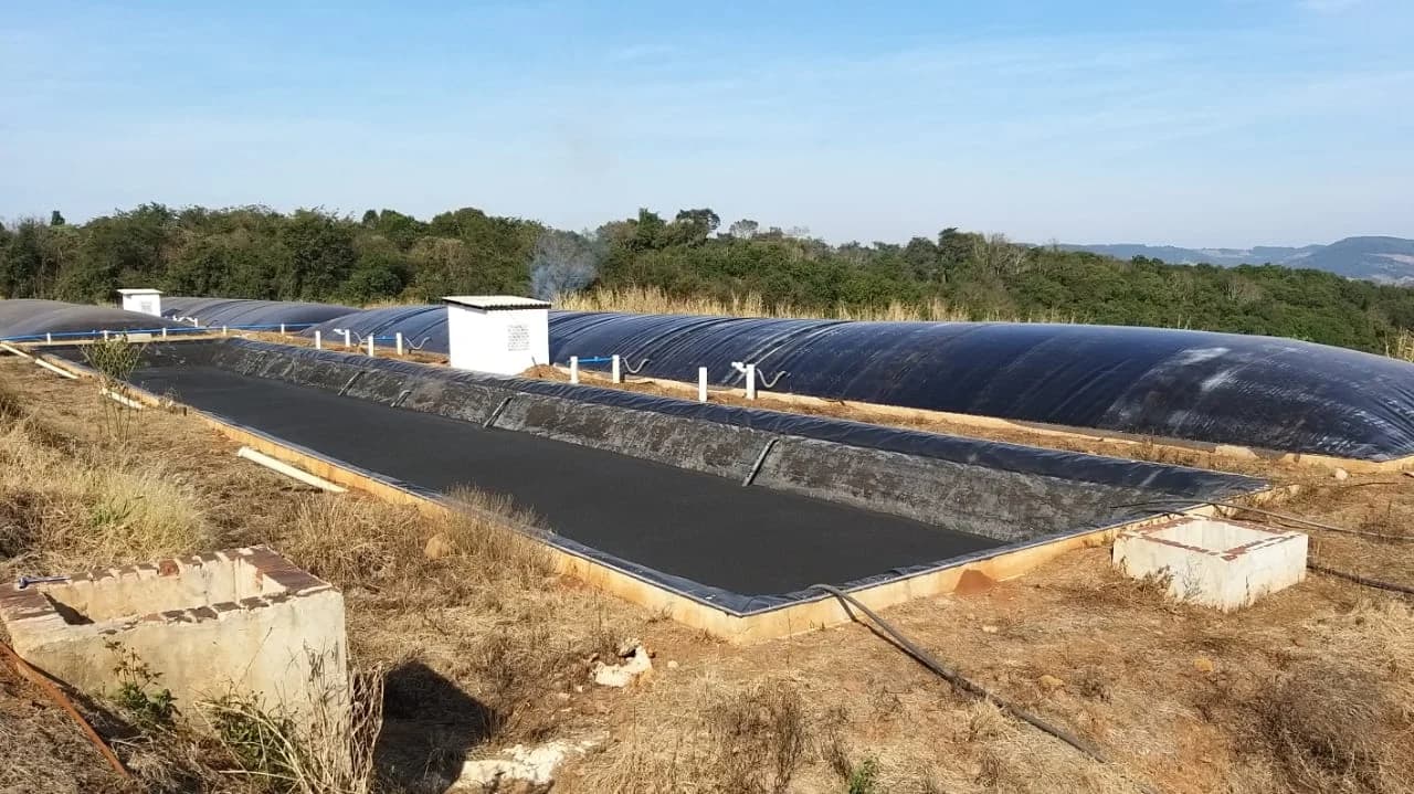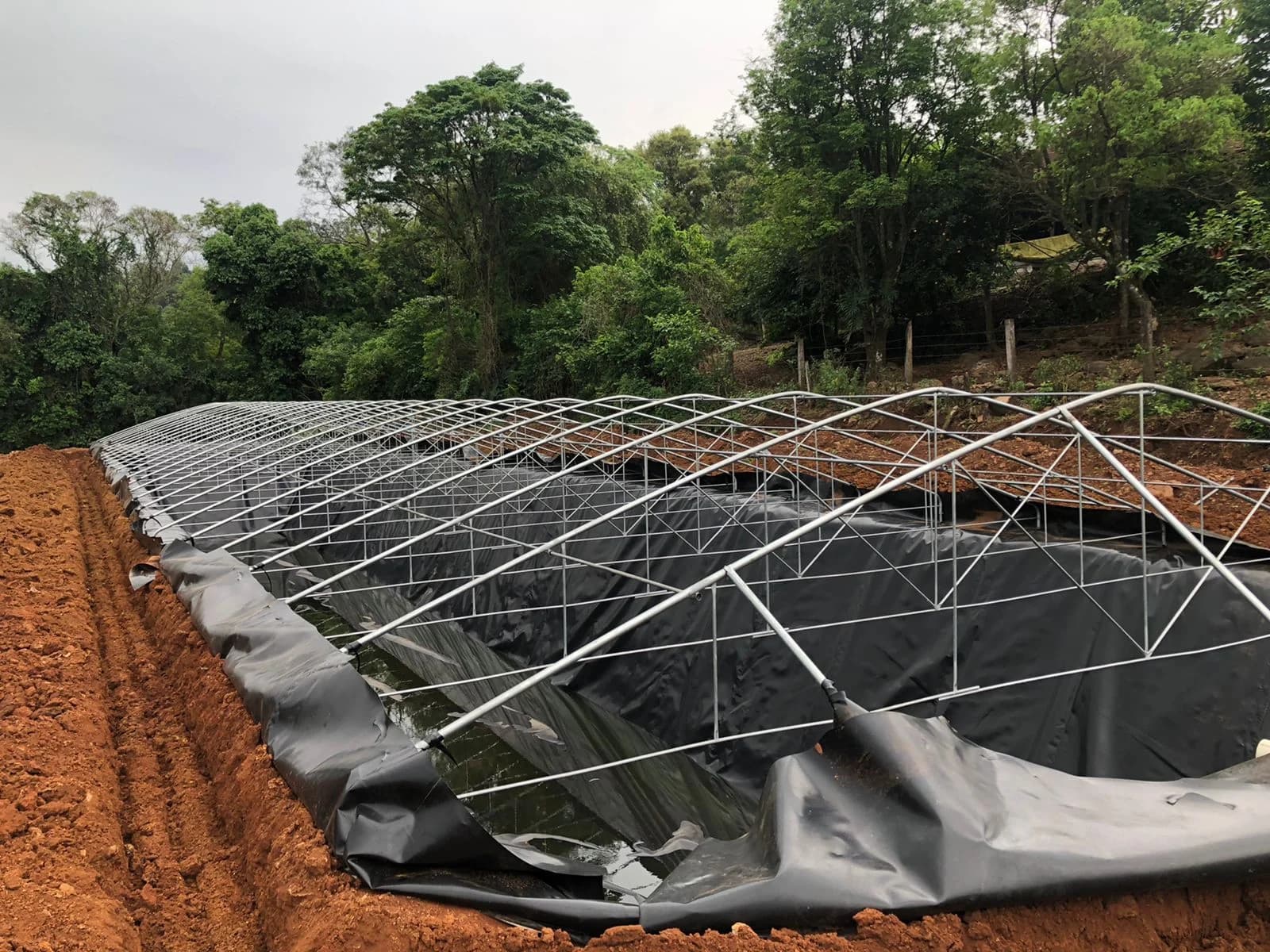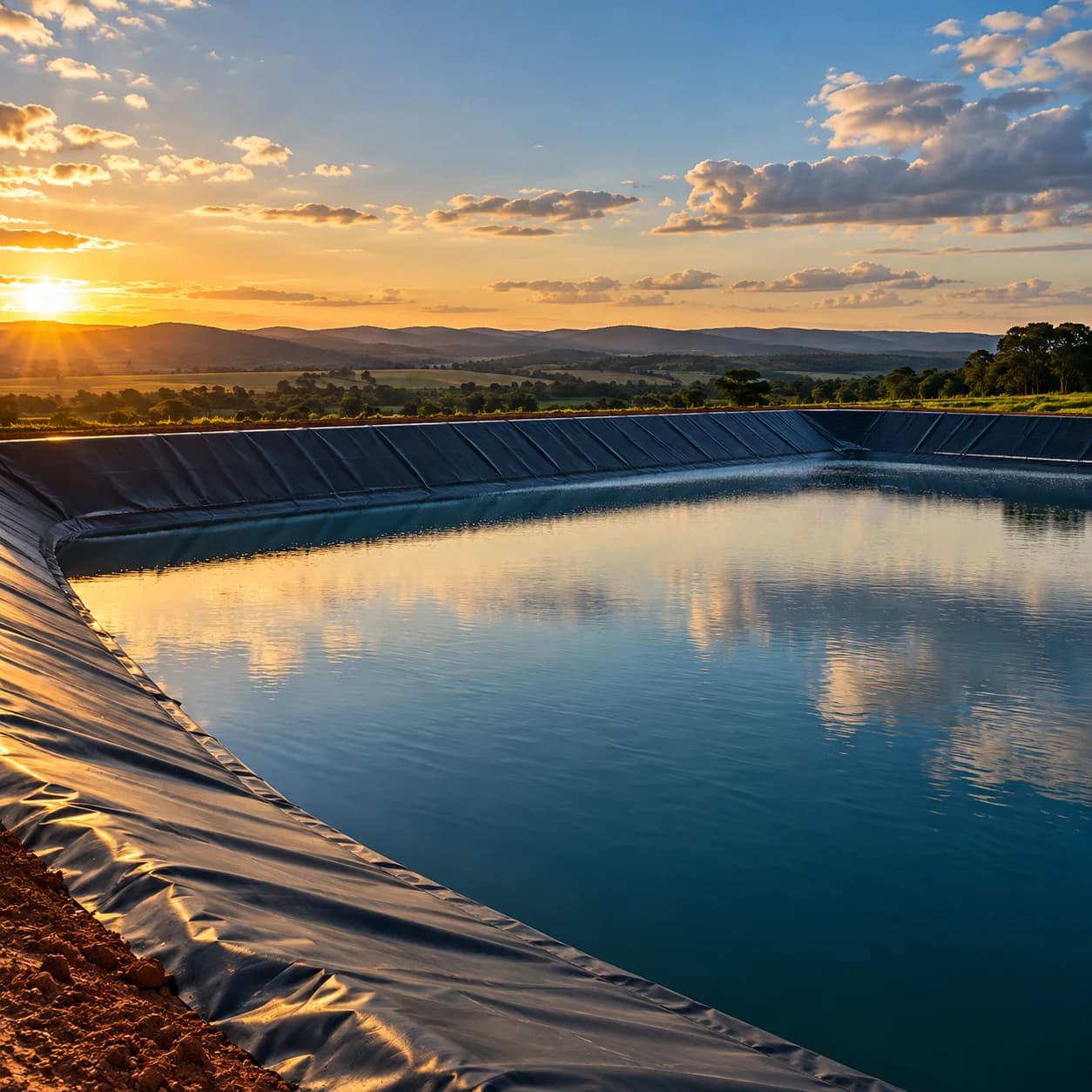
Geomembrane installation is often mistakenly regarded as a quick surface-lining task. In the field, however, synthetic liners act as an engineered containment barrier whose performance relies strictly on foundation conditions, alignment, anchoring, and seaming methods.
When a geomembrane fails prematurely, the issue rarely stems from an intrinsic resin defect; in most cases, it results from unanticipated mechanical stresses during installation, punctures caused by subgrade irregularities, excessive thermal wrinkling, or seams executed without traceable control. Treating geomembrane deployment as an interdisciplinary engineering process significantly mitigates environmental risks and costly rework.
1. Subgrade Acceptance and Basal Protection
Before deploying any panel, the subgrade surface must be formally inspected and signed off. Rough earthmoving completion is not enough: the ground must demonstrate uniform compaction, stable moisture content, and an absence of sharp, puncturing elements.
- Clearing and grading: angular stones, roots, tree stumps, and hard clods with dimensions incompatible with liner thickness must be removed.
- Moisture and mud control: installing over waterlogged or unstable soil compromises machinery traffic, joint geometry, and can induce differential settlement once the structure is filled. Review the detailed steps in how to prepare ground for geomembrane installation.
- Use of a protective layer: when the subgrade contains residual gravel or the project involves high localized loads, pairing the liner with a non-woven geotextile creates a cushioning barrier against mechanical puncture.
2. Deployment Logistics and Panel Orientation
Handling and unrolling geomembrane rolls on-site require careful planning to prevent permanent creasing, surface scratches, and unnecessary material handling.
Panel Orientation on Slopes
In ponds, canals, and containment basins, the primary geotechnical rule is to deploy panels down the slope (from crest to toe), along the line of maximum slope. Horizontal seams across slopes must be avoided, as gravity and tensile stresses concentrate shear forces directly along the seam.
Thermal Effects and Wrinkling
Polymers such as high-density polyethylene (HDPE) have a significant coefficient of linear thermal expansion. Under intense sunlight, the liner expands, forming waves and wrinkles; at night or during cold weather, it contracts sharply.
- Panel placement must account for subsequent thermal contraction, avoiding taut installation during peak sunlight hours.
- If a panel is welded at maximum thermal expansion and rigidly anchored, cooling-induced contraction can pull against the anchor trench or lift the liner at corners (trampolining effect), leaving it vulnerable to tearing under liquid loading.
3. Anchor Trench: Secure Structural Fastening
Anchoring at the crest of the slope holds the panels against sliding caused by self-weight, wind uplift, and construction stresses.
- Trench excavation: dig a continuous longitudinal trench set back at a specified minimum distance from the crest edge (typically between 0.5 m and 1.0 m, according to design specifications).
- Liner placement: the geomembrane must run down into the trench, cover the bottom, and extend up the back wall, lining the inner perimeter of the trench.
- Backfill and compaction: backfill in layers using soil free of sharp stones, compacting manually or with a light vibratory plate to secure the liner firmly without shearing.
- Timing of backfill: avoid permanent backfilling during extreme heat if panels still require alignment adjustments for welding.
4. Seaming Methods: Hot Wedge Fusion and Extrusion
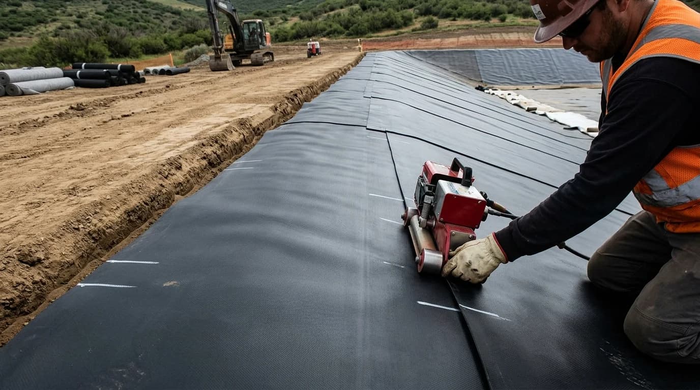
Field welding transforms individual panels into a continuous impermeable barrier. Two complementary methods are standard practice:
Hot Wedge Welding (Dual-Track Thermal Fusion)
This is the primary method for long, uniform seams. The equipment automatically draws overlapping panel edges together, heats the contact surfaces through direct contact with a calibrated metal wedge, and bonds them under pressure rollers.
The standard configuration leaves a central air channel between two parallel weld tracks. This channel allows non-destructive air-pressure testing along the entire seam without damaging the geomembrane.
Extrusion Welding
Used around complex geometries, sharp corners, pipe penetrations, terminations against concrete structures, and localized patch repairs. A bead of molten resin with compatible additives is extruded along a previously abraded joint area.
Before starting each work shift, the crew must perform test seams (trial welds) under representative site and weather conditions to calibrate machine temperature and speed.
5. Quality Control and Field Testing
Barrier integrity cannot be verified by visual inspection alone. A professional geomembrane installation routine combines 100% non-destructive testing on all seams with periodic destructive testing.
| Test | Type | Purpose | Typical Application |
|---|---|---|---|
| Air channel pressure test | Non-destructive | Verify continuity along the dual seam | Long hot wedge welds |
| Vacuum box testing | Non-destructive | Detect pinholes and discontinuities via bubble formation | Extrusion welds, seam details, and patches |
| Spark test | Non-destructive | Locate discontinuities around penetrations and special joints | Complex details with embedded conductive wire |
| Peel and shear testing | Destructive | Measure seam mechanical strength using a field tensiometer | Samples cut from seam ends and shift trial tests |
To explore acceptance criteria and testing parameters in detail, refer to the guide on geomembrane weld quality control.
6. Post-Installation Care and Mechanical Protection
Once welding is completed and continuity tests are approved, the installation enters the operational safeguarding phase:
- Restricted access: prohibit heavy machinery traffic directly over exposed geomembrane. Authorized equipment must only travel over engineered soil cover layers designed specifically for load distribution.
- Interface friction on steep slopes: in landfills or steep slopes scheduled for soil or geocomposite cover, selecting the proper liner texture (smooth vs. textured) is vital to prevent interface slippage, as examined in smooth or textured HDPE geomembrane.
- Penetrations and hydraulic connections: suction pipes, overflow lines, and drains require custom HDPE boots or bolted flanges with neoprene gaskets to guarantee pipe pass-throughs do not become effluent leak paths.
Proper geomembrane application relies on coordinated subgrade preparation, disciplined welding control, and sustained mechanical protection. Executing each detail in strict accordance with project specifications preserves the watertight integrity of the containment system throughout its service life.